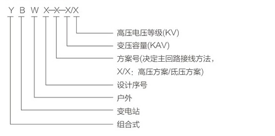
Model Meaning
Product Description
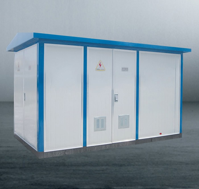
YBW series combined substation is a combination of high-voltage electrical equipment, transformers, low-voltage electrical equipment, etc. into a compact set of power distribution devices, used in urban high-rise buildings, urban and rural buildings, residential areas, high-tech development zones, small and medium-sized factories, mining oil fields As well as temporary construction electricity. It is used for receiving and public distribution energy in the power distribution system.
This product has the characteristics of strong complete set, small size, compact structure, reliable operation, convenient maintenance, and movable. It covers an area of only 1 / 10-1 / 5 of conventional civil substations with the same capacity, greatly reducing construction costs . In the power distribution system, it can be used in the ring network distribution system, and can also be used in the dual power supply or radiation terminal distribution system. It is a new type of complete equipment for the construction and construction of urban and rural substations.
Conditions of Use
1. Altitude: less than 1000m;
2. Ambient temperature:
a. Not higher than + 40C;
b. Not less than 25C;
c. The average temperature within a 24-hour period does not exceed + 30C;
3. The horizontal acceleration of the earthquake is not more than 0.4m / s2, and the vertical acceleration is not more than 0.2m / s2;
4. There is no violent vibration and shock and explosion hazard places.
Structural features
This product is made up of high voltage power distribution device, transformer and low voltage power distribution device. Divided into three functional compartments, namely high-voltage room, transformer and low-voltage room. The high-voltage room has complete functions. The high-voltage room HXGN-10 ring network cabinet forms a primary power supply system, which can not only form a ring network power supply, terminal power supply, dual power supply and other work order methods. For measurement requirements, the transformer can be selected from S9, S11 and other oil-consuming immersed transformers SCB9, SCB10 dry-type transformers. The transformer room is equipped with an automatic forced air cooling system and a lighting system. The low-voltage room can use a panel or cabinet-mounted structure to form the power supply scheme required by the user according to user requirements. This kind of function meets different requirements of users, and facilitates users' power supply management and improves power supply quality.
Non-metal box-type substation
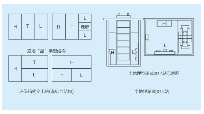
Schematic diagram of ground box substation
The high-voltage, low-voltage and transformer equipments are all below the ground. The equipment can be lifted to remove the large cover. The operator passes through the hole and is suitable for installation in square green belts and parks. It does not affect people's sights and other advantages.
"Mesh" font structure
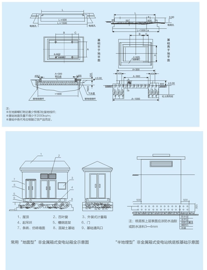
Civil foundation drawing of ground-type non-metal box substation
According to the current international GB / T6451-1999 "Technical Parameters and Requirements of Three-Phase Oil-Immersed Power Transformers" capacity 30-1600kVA, the S13-M.RL series no-load loss decreases by 50% on average, and the load loss decreases by 30% on average -M.RI series no-load loss decreased by 30% on average, and load loss decreased by 25% on average.
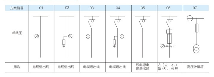
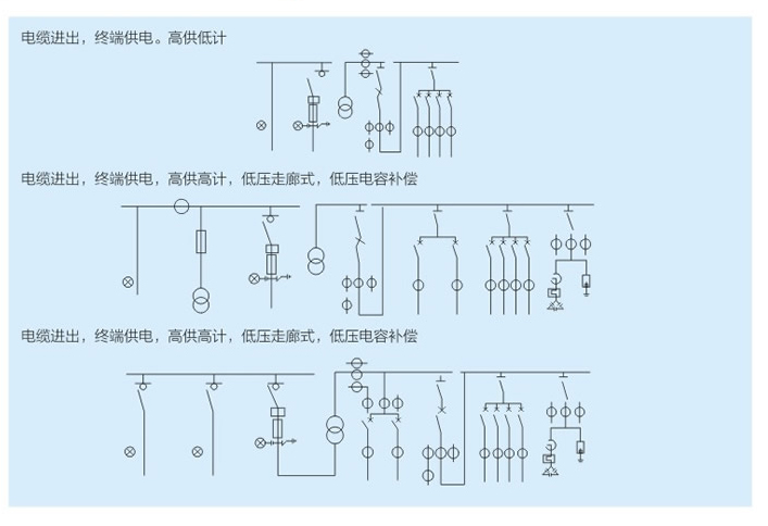
Common scheme of high voltage main circuit
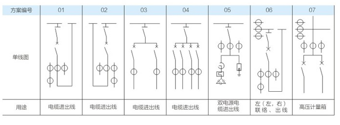
Common scheme of low voltage main circuit
Box-type substation lifting and transportation, use and installation precautions:
◆ The ground around the foundation of the box station should be pre-buried. The transformer and lightning protection grounding can be used together. The grounding resistance is less than 4 days.
◆ Special lifting tools should be used for box-type station lifting, and the lifting parts must be in accordance with the marked parts of the box-type station.
◆ The joint between the bottom of the box station and the foundation needs to be sealed with cement paste to prevent water from entering the cable compartment.
◆ After the wire enters the casing, the gap must be sealed to prevent entry of insects and water.
The box station must check the following before commissioning:
The junction between the bottom of the box-type station and the foundation must be level. If the doors are jammed when opening, this is because the level of the foundation is not flat enough to adjust the combination level of the box-type substation and the foundation. The adjustment method is to fill the gap between the bottom and the foundation of the box-type substation with thin iron sheets until the doors of each room are flexible.
After the assembly of the whole machine is completed, the loading and shipping must pay attention to the distance between the whole box and the front of the car to prevent the car from hitting back and forth due to the brakes on the road. At the same time, the bottom frame and the bottom plate of the box station must be welded Tighten the bottom frame and the bottom line of the car tightly with steel wire, and tie them up and down from the top cover to the bottom of the car with ropes. Where ropes are tied, they must be cushioned with cardboard or other soft objects to prevent damage to the coating surface.
In order to keep the box station in operation intact, the interior and exterior must be cleaned and wiped once every six months or a year. If it is found that the external surface of the box is soiled during installation or transportation, it can be scrubbed with detergent and rinsed with clean water.
Examples of typical system solutions
Download Google
Please provide the following information when ordering:
1. Model of box-type substation and cable distribution box;
5. Shell color;
2. Transformer model and capacity;
6. Name, quantity and other requirements of spare parts and spare parts;
3. High and low voltage main circuit wiring scheme diagram;
7. Provide high- and low-voltage cable cross-section areas;
4. Models and parameters of electrical components with special requirements;
8. There are special requirements to provide secondary schematic diagrams and wiring diagrams;

